Segmentation And Label Cleanup
Segmentation workflows usually turn an intensity image into a mask, then into labels.
For a cross-cutting worked example, see Separate overlapping objects: segment two structures from one synthetic image, reconstruct a curve with binary logic, then create meshes.
Basic Pattern
For exact histogram populations, Minimum/ImageJ behavior, and numeric limits, see intensity and threshold controls.
Image Source
  -> Extract Channel or Split Channels
  -> optional background correction / denoising
  -> threshold
  -> morphology cleanup
  -> Label Connected Components
  -> label filtering
Recommended First Graph
Image Source
  -> Split Channels
  -> Gaussian Blur
  -> Otsu Threshold
  -> Fill Holes
  -> Remove Outliers (Binary)
  -> Remove Small Objects
  -> Label Connected Components
  -> Filter Labels By Volume
Key Nodes
| Step | Common nodes |
|---|---|
| Channel selection | Extract Channel, Split Channels |
| Smoothing | Gaussian Blur, Gaussian Blur 3D, Median Filter, Sigma Filter, Non-Local Means |
| Background | Rolling-Ball Background, Subtract Background |
| Threshold | Otsu Threshold, Triangle Threshold, Li Threshold, Yen Threshold, Binary Threshold, ImageJ Default Threshold (8-bit), local threshold nodes |
| Mask cleanup | Fill Holes, Remove Outliers (Binary), Remove Small Objects, morphology nodes |
| Label creation | Label Connected Components, watershed nodes |
| Label cleanup | Clear Border Objects, Filter Labels By Volume, Filter Labels By Property, Relabel Sequential |
| Boundary QC | Find Label Boundaries (new in 0.15.0a3) |
Read object counts
New in 0.15.0a3
Select Remove Small Objects, Clear Border Objects, Filter Labels By Volume, or Filter Labels By Property to review input, kept, and removed object counts in the inspector's Filter result section, after the input/object histogram so Parameters and the histogram stay together.
The counts compare the node's actual input and current calculated output. They are not a prediction from the sliders. After changing settings, calculate the node if needed; an old or missing output cannot provide current kept/removed counts. Bypassing the node does not claim that its filter was applied.
For label images, objects are distinct positive label IDs, not the largest ID. For Boolean masks, they are connected components using the operation's connectivity. Counts follow the selected 2D/3D processing scope, with independent time points, channels, or slices counted separately. Background is excluded.
Counting runs in the background and does not change the segmentation. Continue to inspect the result: a kept/removed count cannot determine whether an object is biological or whether the chosen filter is appropriate.
Inspect label boundaries
New in 0.15.0a3
Label Operations → Find Label Boundaries creates a Boolean boundary mask for QC overlays or saving. It does not create a mesh or detect edges in an intensity image.
- Branch a label output into Find Label Boundaries. Boolean masks are also
accepted; integer labels must be non-negative, with
0as background. -
Choose Boundary placement:
Choice What is marked Inside objects (default) Object-side boundary pixels/voxels, including interfaces between different labels. Outside objects Background-side boundaries, plus interfaces between touching non-zero labels; this is not strictly a background-only mask. Both sides Both sides of a label transition, giving a thicker boundary. -
For stacks, review Spatial processing. Auto from axes follows the interpreted axes; resolve ambiguous axes first. 2D per XY slice (advanced) treats each plane independently; 3D ZYX volume includes changes along Z. These may appear as 2D YX/3D ZYX before axes resolve. Time points and channels are always processed independently. If axes are interleaved (for example ZCYX for volume processing), use Reorder Axes explicitly when requested; the node does not rearrange them automatically.
- Use Face connected for side/face-sharing neighbors (4 in 2D, 6 in 3D), or Full connectivity to include diagonal neighbors (8 in 2D, 26 in 3D).
- Inspect or pin the mask over the source image, or connect Save Image or Batch Output as with any other mask.
Keep the original labels for object measurements: the boundary output has only true/false values and does not retain object IDs. It has the same shape, axes, spacing, units and origin as the input; calculation leaves upstream labels unchanged and runs on CPU.
VIPP does not pad the image with imaginary background. An object touching the
crop edge is not automatically outlined along that edge; only transitions
within the image are available. Boundary thickness is defined on the pixel/voxel
grid, not by a physical-distance setting, so anisotropic voxels do not make a
uniform physical-width shell. The placement modes follow scikit-image's
find_boundaries
(inner, outer, thick respectively, with background 0).
Convex Hull
Morphology → Convex Hull fills the smallest convex envelope around the foreground of a Boolean mask, such as a threshold output.
- Connect your threshold or other Boolean mask to Convex Hull.
-
Choose Spatial processing when working with a stack:
Choice Result Auto from axes Uses the declared image axes to choose planes or volumes. Ambiguous stack axes must be resolved first. 2D YX Forms a separate hull in each slice; does not fill between slices. 3D ZYX Forms a volume hull, including foreground across Z slices. -
Inspect the result before using it for measurements. All foreground in each plane or volume contributes to one hull: separate objects can join, and concavities and enclosed gaps can be filled. This is not a per-label operation or a replacement for ordinary hole filling.
Time points and channels are processed independently. The output is a Boolean mask on the unchanged image grid, with the original spacing, units and origin. Empty masks remain empty; isolated points, lines and flat 3D masks are supported. Intensity and label images must be thresholded explicitly first.
The CPU implementation follows scikit-image's binary hull convention: half-pixel offsets along each spatial axis, with hull borders included. Tests cover analytical shapes and reference parity; flat 3D inputs have additional handling.
Rasterization is chunked, but large or complex hulls can still need substantial time and memory. Cancellation is checked between stages and chunks; an active native hull calculation must return first. Applying this rasterized hull repeatedly can expand its boundary further, so normally use one hull node.
How Global Automatic Thresholds Use The Data
Otsu Threshold, Triangle Threshold, Yen Threshold, Isodata Threshold,
and Minimum Threshold calculate from every finite value in the selected
scope. VIPP does not estimate these thresholds from a pixel sample.
| Input | Scientific behavior |
|---|---|
| Boolean mask | The input is already a segmentation, so VIPP preserves its True/False decisions instead of thresholding it again. |
| Integer image | Every native integer level from the observed minimum to maximum receives its own bin. This is exact for spans of up to 65,536 levels. |
| Floating-point image | All finite values are counted into the saved Float histogram bins setting: 2–65,536 bins, with 256 as the default. |
| Li threshold | Li operates iteratively on the raw finite intensity values and does not have a histogram-bin setting. Integer inputs retain exact native offsets; a relative span wider than 2^53 reports an error because Li's float64 iteration cannot represent every level faithfully. |
For a wide integer image whose observed range spans more than 65,536 levels,
VIPP stops with an explanatory error. It does not silently merge integer
levels. Convert or rescale deliberately to uint16 or floating point, record
that step, and inspect its effect before thresholding.
NaN, positive infinity, and negative infinity are excluded while an
automatic threshold is calculated. Those pixels become False (background)
in the output mask. An empty input or one containing no finite values reports
an error instead of receiving an invented cutoff.
The float bin count is a method parameter
For floating-point data, changing Float histogram bins can change the threshold and the resulting mask. The value is saved in the workflow. The bins drawn in the inspector are a separate display choice and do not replace this setting.
Practical bin guidance
- For
uint8,uint16, or another integer image with a range of at most 65,536 levels, leave Float histogram bins alone: integer levels are counted natively regardless of that float-only setting. - For floating-point images, start with the saved default of 256. On the development set, compare scientifically plausible alternatives such as 256, 1,024, and 4,096 when the decision appears bin-sensitive.
- Do not assume that the largest allowed value is automatically best. More bins can make a sparse or noisy histogram less stable.
- Freeze and report the selected value with the threshold scope and preprocessing steps.
For example, a methods record might state: “Otsu thresholding used the complete
float32 stack with 1,024 histogram bins; non-finite pixels were treated as
background.”
ImageJ Default Threshold is a separate conversion path
ImageJ Default Threshold (8-bit) is an explicit experimental compatibility node
targeting ImageJ 1.54p's modified IsoData (Default) behavior. It first follows the
declared per-plane 8-bit conversion for scalar uint8, uint16, or float32,
then thresholds that result. It does not change the generic VIPP Otsu,
Triangle, Li, Yen, Isodata, or Minimum nodes.
The public node no longer exposes a method dropdown. An older saved workflow
that selected ImageJ Triangle retains that distinct calculation as fixed
legacy compatibility; loading does not silently replace it with Default. Use
the new public node deliberately when choosing the Default method.
For Minimum Threshold, “Minimum” means the valley between two histogram peaks, not the image's minimum pixel value. Its smoothing operates on the histogram, not the image. The convergence limit is an early-stopping safety limit, not smoothing strength; a distribution that does not resolve two peaks can fail. Keep the scientific Stack/Slice threshold scope separate from the inspector histogram's display scope.
Boolean handling and RGB/RGBA luma reduction are VIPP extensions and are not claimed as ImageJ-exact. Infinite floating-point inputs are rejected. Independent ImageJ-generated golden parity is pending, so record the node explicitly and compare against the intended ImageJ reference before consequential use.
CPU and GPU boundaries in this workflow
Extract Channel, exact Preserve dtype conversion, Gaussian, Binary Threshold,
Boolean Remove Small Objects, Boolean Fill Holes, connected components, Otsu,
Canny, median, Sigma Filter, Remove Outliers (Binary), and background correction
have GPU candidates only inside declared regions. The portable corridor
introduced in 0.13.0a8 can use an explicitly described
channel, convert uint8/uint16 to float32 without rescaling, apply Gaussian
Blur and an exact finite Binary Threshold, clean the Boolean mask, and label it
without an intermediate host transfer.
Prefer GPU keeps a first-step Extract Channel on CPU so only the selected
channel is uploaded. Remove Small Objects supports Boolean masks in resolved
2D/3D Face or Full connectivity; integer-label cleanup remains CPU. Fill Holes
supports those Boolean connectivity regions only when Maximum hole size = 0;
a positive bounded size remains CPU. Connected Components still requires a
Boolean call resolved as 2D or 3D. Unsupported calls receive an explained CPU
decision, while invalid or explicitly non-fallback-safe calls fail planning.
Remove Outliers (Binary) processes each trailing YX plane independently using
Fiji-compatible circular neighborhoods. Choose foreground removal to clean
bright specks or background filling to close dark notches. The public CuPy
region accepts Boolean masks and radius 0.5–25; canonical uint8 masks and
larger valid radii use CPU. Review fine boundaries at the intended zoom because
this majority cleanup can remove real thin structures.
VIPP never inserts a cast during calculation. When dtype is the only reviewed blocker, the node may show a GPU tip and an Add conversion button. That button inserts a visible, undoable Convert Dtype node; review its memory, threshold, and scientific consequences before accepting it.
Read each node badge after calculation and see the CPU/GPU operation matrix before authoring a provider choice. GPU eligibility says that an implementation matches its declared CPU contract; it does not validate the segmentation for your assay.
Minimum Threshold Failure Is Explicit
Minimum Threshold repeatedly smooths the exact histogram until two maxima
remain, then selects the valley between them. Histogram smoothing pass limit
is a saved parameter from 1 to 10,000; the default is 10,000.
Some distributions do not have a suitable two-peak solution. If two maxima cannot be found, or the saved iteration limit is reached, the node reports a failure. VIPP does not silently substitute Otsu, reuse an old threshold, or return a plausible-looking mask. Treat the failure as evidence that this method is unsuitable for that input or that preprocessing needs review.
2D Versus 3D
For z-stacks, decide whether objects should be connected across Z.
- Use 2D processing when each
YXplane should be independent. - Use 3D processing when the object exists as one
ZYXvolume. - Use
Auto from axesonly after checking that VIPP has interpreted the axes correctly.
Split Touching Objects
Use watershed when simple connected components merge neighboring objects:
mask
  -> Euclidean Distance Transform
  -> H-Maxima Markers
  -> Marker-Controlled Watershed
  -> Filter Labels By Volume
For a compact single-node starting point, use Auto Watershed From Mask.
Reference Workflow
To turn a finished volume mask into a viewable/exportable surface, see Create, colour and export 3D mesh objects.
Use the general cleanup example:
This demonstrates red/TRITC-like channel segmentation, mask cleanup, labels, border clearing, volume filtering, and inspectable outputs.
To inspect the coherent Prefer-GPU corridor and its CPU fallbacks, open Portable GPU Segmentation Bridge or use:
Its deterministic sample contains four retained 3D objects, one 19-voxel speck removed by the authored 22-voxel cutoff, and one 31-voxel enclosed cavity restored by Fill Holes. Those facts make each cleanup step independently inspectable; they do not validate the thresholds for another dataset.
What To Check
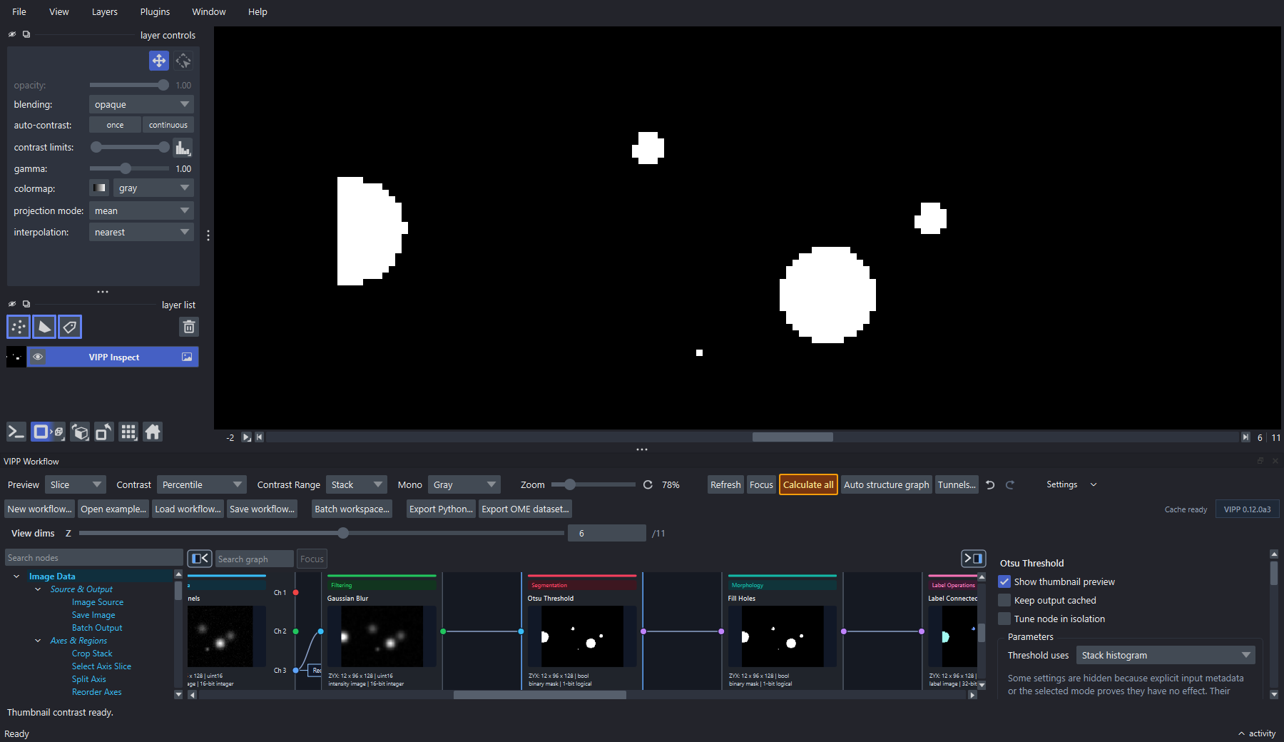
Inspect a decisive intermediate at full resolution. Here the threshold mask is pinned in napari while its graph node remains visible and the selected Stack histogram scope is recorded in the inspector history.
- Does the mask include the biology of interest?
- Are background/noise structures being labeled as objects?
- Are touching objects merged?
- Are small objects biological or artifacts?
- Are physical units correct before size filtering or measurement?